Altium Integration
Altium Integration
Overview
Empower provides the following methods for integrating Altium Designer to the Empower Empower system:
| Method | Description |
|---|---|
| Database Library | Database Libraries allow you to link component information stored in a database to schematic symbols. When using database libraries, the user will be able to search for parameters and place components on designs with parameters populated with values from the database. |
| CADKit Extension | Empower provides an Altium Designer Extension to perform the following operations:
|
Database Library
Database Libraries allow you to link component information stored in a database to schematic symbols. When using database libraries, the user will be able to search for parameters and place components on designs with parameters populated with values from the database.
To link Altium libraries to the Empower database you must perform the following steps:
- Create database views using the Empower View Manager
- Create and configure a Database Library in Altium Designer
Create Database Views in Empower
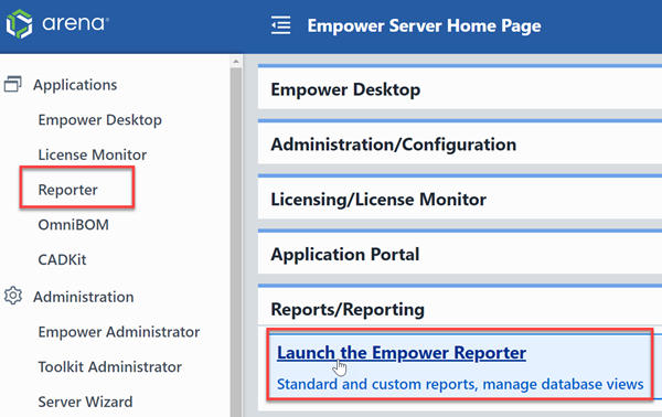
To create database views in Empower, from the Empower Server Home Page click the Empower Report link.
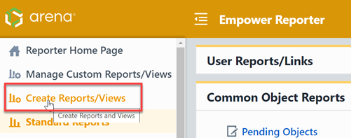
From the Empower Report Home Page, select the Create Reports/Views link.
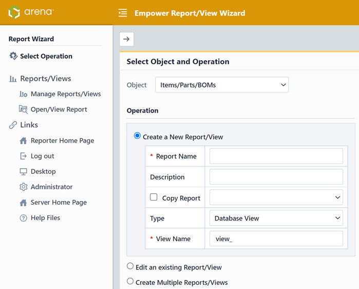
Using the View Manager, you will be able to create single or multiple views, select fields, and define search/filter criteria.
Refer to the View Manager User's Guide for more information on creating database views.
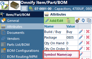
Note: when creating views, you must include an Empower field (attribute) that identifies the name of the schematic component.
Create Database Library in Altium
Once database views have been created using the Empower View Manager, you can then create an Altium Database Library to instantiate components in Designer with information in the Empower database.
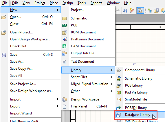
To create a Database Library, select the File -> New -> Library -> Database Library command from Altium Designer.
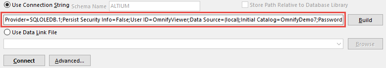
From the Database Library form, select the Use Connection String option.
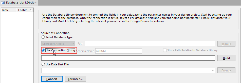
If you don't know the Connection String, you can click the Build button.

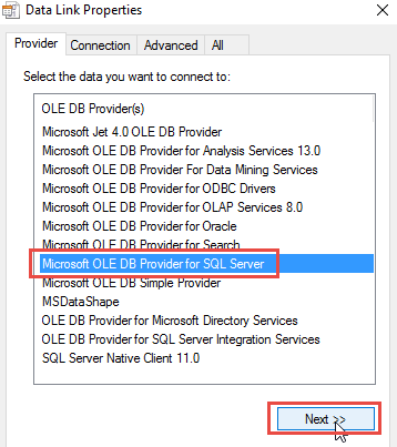
From the Data Link Properties wizard, select the Microsoft OLE DB Provider for SQL Server and then click the Next button.
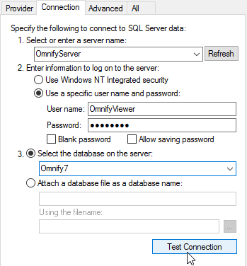
On the Connection tab, specify the Server name, User Name, Password, and Database Name. Contact your Empower Administrator if you do not know these settings. You can test the settings by clicking the Test Connection button. Once the properties have been set, click the OK button to return to the Database Library form.
The Connection String will be assigned.
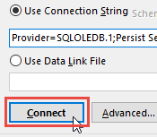
Click the Connect button to connect to the database and list the available tables and views.
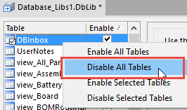
The available tables and views will be listed.
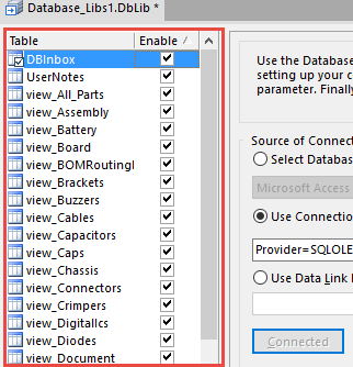
From the available tables/views list, click the right mouse button and then select the Disable All Tables command.
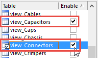
You can then select/check the desired views (created using the View Manager).
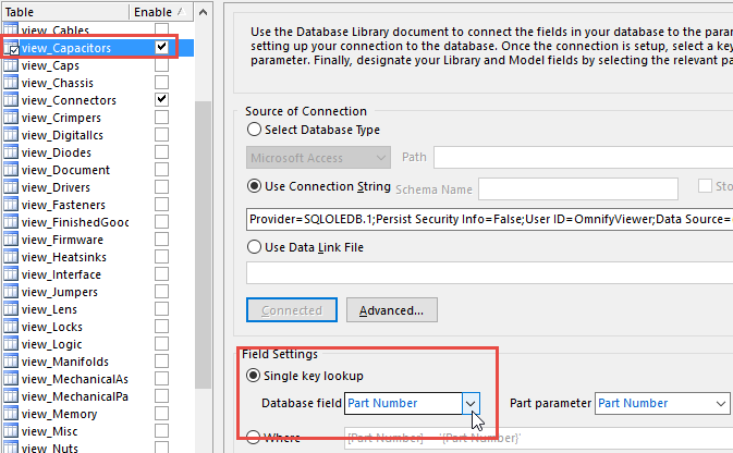
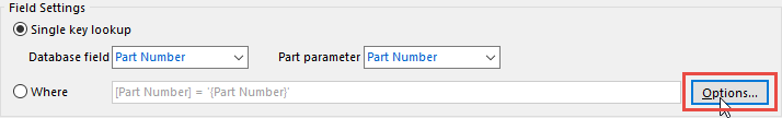
To set the table and field properties, select the enabled view and then set the Part Number as the key field in the Field Settings section.
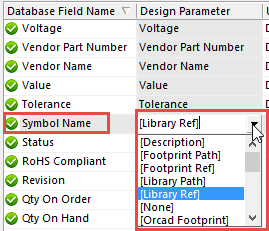
You can then configure the view fields to map to specific Designer fields.
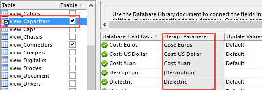
The library will require that the [Library Ref] parameter be assigned to the symbol name field/attribute in Empower.
To define the symbol library search path, select the Options button in the Field Settings area.
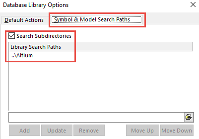
From the Database Library Options dialog box, select the Symbol & Model Search Paths tab, and define the library search paths
You can save the Database Library file once all settings have been defined.
The Database Library will now be available in the Library list.
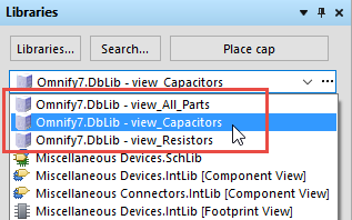
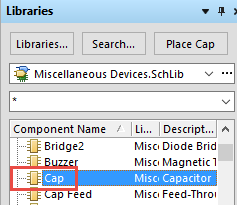
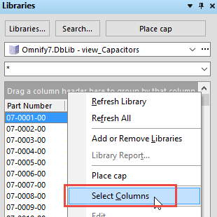
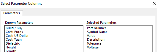
Selecting the Library, will display the fields and provide a search option. You can change the search/display fields by clicking the right mouse button and selecting the Select Columns command.
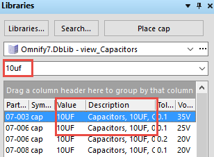
You will then be able to search the selected fields.
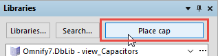
To place the component, click the Place button and then move the cursor to the schematic.
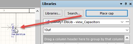
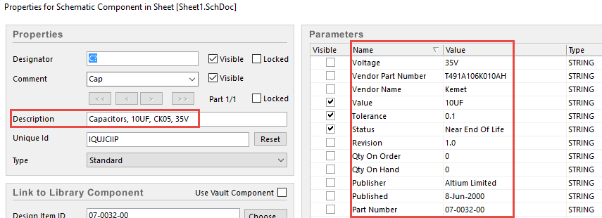
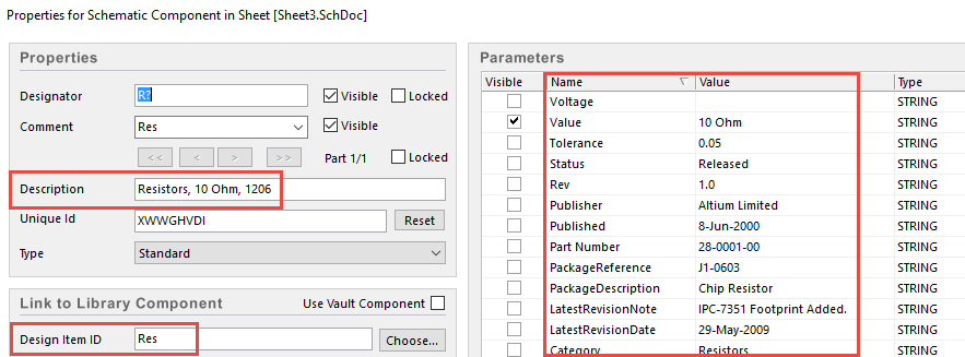
Notice that all of the enabled fields and values from the Empower database will now appear as parameters on the placed component.
Designer Extension
Empower CADKit includes an Altium Designer Extension that allows users to add and update schematic components from the Empower database, as well as create BOMs to be uploaded to the database.
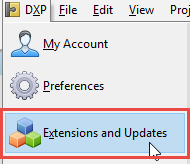
You can install the CADKit Extension by selecting the Extensions and Updates command from the DXP menu.
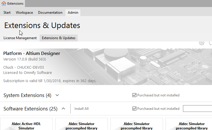
From the Extensions form you will be able to install the Empower CADKit Extension.
Launching the Extension
Once the CADKit Extension has been installed, the Designer menus and toolbars will be updated with links to Empower CADKit. These option will be available when a schematic is the active document in Designer.
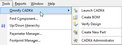
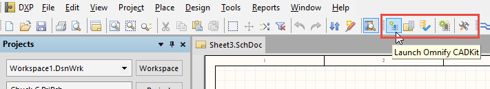
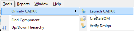
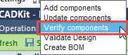
The Tools menu and toolbar will contain the following commands:
| Command | Description |
|---|---|
| Launch CADKit | Launches CADKit and selects the Add Components operation |
| Create BOM | Launches CADKit and selects the Create BOM operation |
| Verify Design | Launches CADKit and selects the Verify Design operation |
| Create New Part | Reads the selected components and launches the new part request form |
| CADKit Administrator | Launches the CADKit Administrator |
Note: all commands/operations will be described in the following sections.
Selecting any of the commands will launch the CADKit Altium Adapter.
When you launch CADKit for the first time, you will be presented with the Settings page.
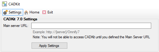
You must set the Main Server URL option before CADKit will direct you to a specific form. Set the Main Server URL option to the Empower Server installation URL. Contact your Empower Administrator if you do not know the URL. The URL should be something similar to: http://[Empower_Server_Name]/Empower8.
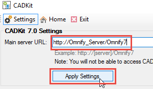
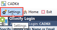
Click the Apply Setting button, to be redirected to a CADKit form. You can always return to the Settings form by clicking the Settings toolbar button.
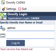
When the adapter is invoked, CADKit will begin communicating with the Altium Designer application. You will also be asked to log in with your Empower database credentials, if not already.
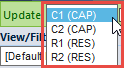
When using the Adapter, the user can select from 5 different operating modes:
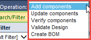
| Mode | Description |
|---|---|
| Add Components | Allows you to add components to a Designer schematic with properties of an item from the Empower database |
| Update Components | Allows you to update previously placed components on a Designer schematic with properties of an item from the Empower database |
| Verify Components | Finds matches for all schematic components to items in the Empower database |
| Validate Design/Components | Compares properties of components on a Designer schematic with items in the Empower database to determine if a unique match exists. |
| Create BOM | Creates a Bill of Material from the schematic to be saved or uploaded to Empower/OmniBOM |
Form Basics
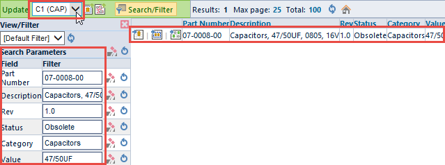
The Altium Designer Adapter form contains the following areas:
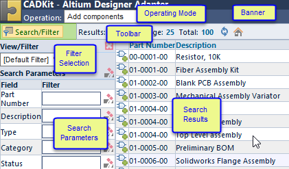
| Area | Description |
|---|---|
| Banner | Displays Altium Designer connectivity, version, and current design information. |
| Operating Mode | Allows you to select from the various operating modes |
| Saved Filter Selection | Allows you to select from a saved filter/parameters |
| Toolbar | Access to common Adapter commands |
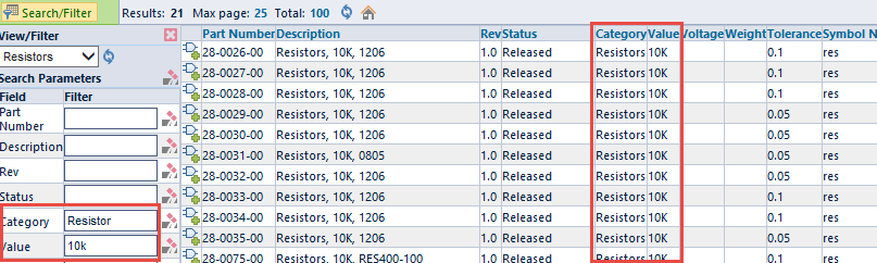
| Search Results | Displays the results of the Empower database search |
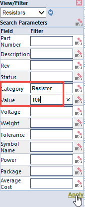
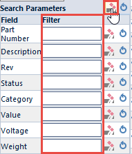
| Search Parameters | Allows you to search the Empower database and filter the results list based on specific data field values |
Note: the Results area may change based on the selected Operating Mode.
Fields/Attributes
The Altium Designer adapter allows you to assign each schematic component to a matching Item in the Empower database. For the adapter to match a schematic component to an Empower Item, the Part Number field must be assigned as an attribute to the schematic component.
When adding or updating schematic components, the Adapter will automatically assign the attributes specified in the CADKit Administrator. These fields will appear in the Search Parameters pane.
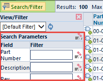
These fields will also be assigned as attributes to the components during Add and Update operations.
Views/Filters
"Views" or "Filters" can be created that provide default field search parameters and field configurations. "Filters" are created and configured in the CADKit Administrator. Each filter will appear in the View/Filter drop list.

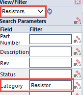
Once a filter is selected, the default search parameters and settings will appear in the Search Parameters list.
Searching
When adding or updating components on an Altium Designer schematic, the database search list will be displayed on the Adapter form.
You can define search parameters by typing a search value in the Search Parameters list, and then clicking the Apply button/link.
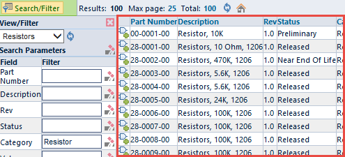
The Search Results list will update to display the matching database items.
By default, the system will automatically include wildcards (e.g. "res" is equivalent to "res"). You can manually assign wildcards by specifying * or % on any of the fields (e.g. "res*" will return anything that starts with "res").
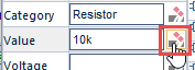
You can clear any field by clicking the clear icon on any field.
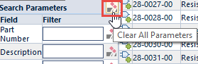
You can clear all search parameters using the Clear All icon in the Search Parameters header.
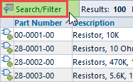
You can sort on any column by clicking the Column header hyperlink.

The sort icon will appear to the right of the currently sorted column.

The Results list will be presented in a paging mode. You can define both a maximum record return and page size option for the results.
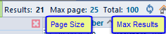
If the return records exceed the page size, the system will display a page navigator that allows you to switch between various page results.


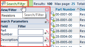
You can show and hide the Search Parameters pane by selecting the Search/Filter toolbar button.
Adding Components
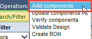
To add components to an Altium Designer schematic from CADKit, select the Add components operating mode.
Refer to the Searching the Database section for more information on refining your searches.
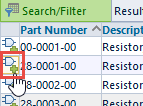
To add a component to the schematic, click the Add icon on the desired row.
You can now move the cursor to the schematic window.

The new component will be attached to the cursor.
Click the left mouse button in the schematic window to place the component.

The system will look at the Symbol field setting (Administrator Options) to determine which column contains the symbol name to be used when placing the component.
If the symbol specified in Empower does not exist in your library search path you will receive the following error:
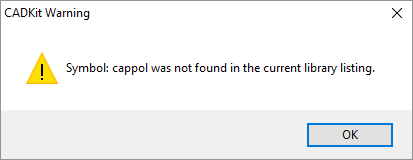
If this error appears, check your library settings to validate that the desired part type is available in your library listing.
When adding the component to the schematic, CADKit will apply all desired field/field values from the view as attributes on the component.
If you attempt to add a component where the symbol field is not defined, the Toolbar will indicate that the symbol field is not defined.

Updating Components
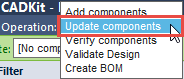
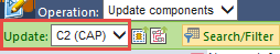
To update components that have already been placed on a Designer schematic, select the Update components mode.
Note: a components (Update:) drop list will appear in the toolbar.

By default, CADKit will list the components that are selected in the schematic. You can load the Update drop list with the selected or all design components.
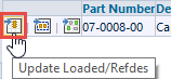
To load the Update drop list with the selected component(s), first select the desired component(s) in the schematic and then click the Load Selected Components toolbar button.

To load the Update drop list with all design components, click the Load All Components toolbar button.

The Update drop list will display the Reference Designator and Part Type for each component.
Once a component is selected in the drop list, the system will read all "Load" attributes from the schematic and use them as search parameters. The system will then display all matching results in the Search Results list.
You can use the searching techniques discussed in the Searching the Database section for more instructions on expanding or narrowing your search results.
When updating the components, you can update the loaded component (component selected in the Update drop list), all "like" components (same part type), or the selected (on the schematic) components.
Updating Loaded Component
Once you have identified the appropriate item, you can click the Update Component icon on the desired row.
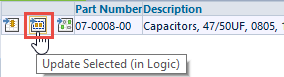
Updating Selected Components
Once you have identified the appropriate item, you can update the currently selected components in the schematic by clicking the Update Selected Components icon on the desired row.
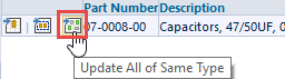
Updating "Like" Components
Once you have identified the appropriate item, you can update all design components that have the same part type by clicking the Update All of Same Type icon on the desired row.
Note: when updating components, the Adapter will automatically swap decals if a "Decal" field is defined for a field.
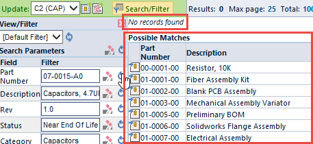
Possible Matches
When updating components, if you provide search parameters that do not have an exact match in the database, the system will display a list of possible matches.
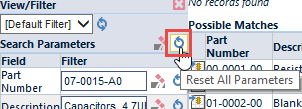
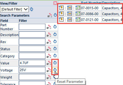
You can update the component from the Possible Matches list, or you can eliminate/apply field values to find a better match. In update mode, the adapter will provide a Reset Parameter icon for each field in the Search Parameters list, as well as a Reset All Parameters from the section header.
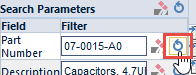
You can clear all or some of the parameters using the Clear icons:
And then reset specific search fields until you find a desired component.
Verifying Components
The PADS Logic Adapter contains a part verifier. The verifier will load components from a design to the BOM Form window and then search the Empower database to find matching part numbers. To launch the Verifier, select the Verify components operating mode.
The results list will display the Verifier form.
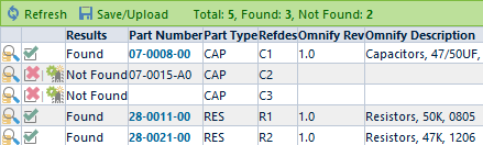
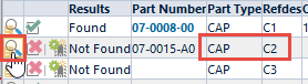
The verifier will read and list all components in the Logic schematic. When loading the verifier, the system will determine the Part Number for each component based on the Attribute settings. Part Number attributes are defined/mapped using the CADKit Administrator.
The Results column will display the results of the verification.
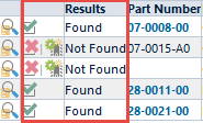
For components that have been verified, a hyperlink will be provided that will open the item in Empower in a separate web browser window.
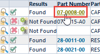
For components that could not be verified, selecting the Search/Update Component icon in the list will load the item in Update Components mode.
Note: you can configure CADKit to ignore components for verification/BOM generation. Refer to the CADKit Administrator section for more information on ignoring components.
Validating Design
The Component Validator will read the attributes of the desired schematic components and compare them to the database to determine if each component has a unique match in the database.
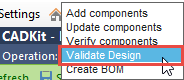
To execute the Component Validator, select the Validate Design option from the Operation drop list.
The Validator will load all component values and begin searching the database for matches.
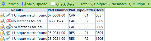
The Results list will display all loaded components and the results of the search.
Each component will have the following result options:
| Icon | Result | Description |
|---|---|---|
 | 1 Unique match found | All component properties contain a single match/item in the database |
 | X (number) matches found | Not enough properties on the component to derive a single match/item in the database |
 | No matches found | Properties on the component do not result in any matches in the database. |
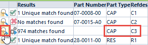
Clicking the Search/Update icon in the results list will load the component and switch to the Update Component mode.

Note: you can configure CADKit to ignore components for validation. Refer to the CADKit Administrator section for more information on ignoring components.
Uploading BOM
To create a BOM from a Logic design, select the Create BOM option from the Operation drop list.

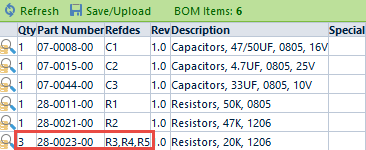
This will read all components in the current design and display a BOM form listing all components.
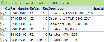
The BOM creation will automatically condense all like items (same part number) to a single BOM item and update the quantity and refdes fields.
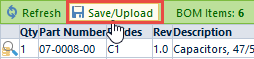
Once the BOM is created, you can Export or Upload the BOM directly to Empower/OmniBOM. To Export or Upload the BOM, select the Save/Upload toolbar button.
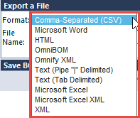
In the Save/Export Results area, you will be able to export to a variety of formats.
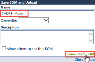
To upload the BOM directly to an Empower item or Change/ECO, select the Save BOM and Upload option.
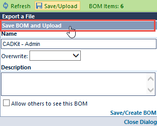
To upload a BOM, you must define a Name to the BOM and then click the Save/Create BOM button.
Once the BOM has been saved, you can select the upload configuration and then click the Upload to Empower button.
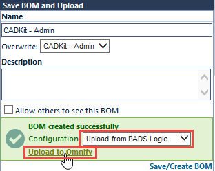
The Design Upload Utility will be launched and the BOM will appear.
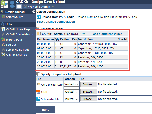
The Design Upload Utility will allow you to specify parent items and Changes/ECOs.
Refer to the Design Upload Utility section for more information on using the Upload Wizard.
When creating the BOM, the system will determine the Part Number for each component based on the Attribute settings. Part Number attributes are defined/mapped using the CADKit Administrator.
Note: you can configure CADKit to ignore components for BOMs as well as define "disabled" BOM items. Refer to the CADKit Administrator section for more information on ignoring components.