Administration
Administration
Overview
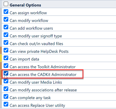
All CADKit options and field settings are controlled and modified using the CADKit Administrator. CADKit Administrator access is granted/denied by the User Permission groups in the Empower Administrator (General Options section).
Launching
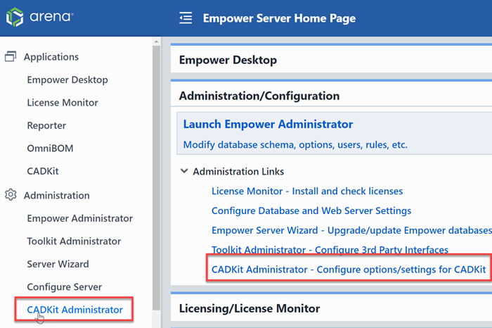
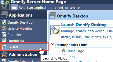
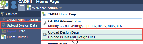
You can launch the CADKit Administrator directly from the Server Home Page.
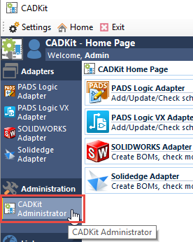
You can also launch the CADKit Administrator from the CADKit client Home Page (this will launch a separate web browser window).
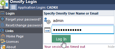
The standard web browser login will appear.
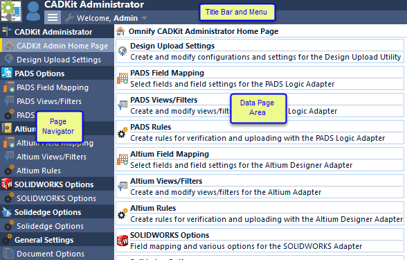
Once you have logged in, the CADKit Administrator form will contain the following key areas:
Basics
The main form contains a page navigator that allows you to view specific data pages. Selecting an option page from the navigator will display that page in the Data Page area.
The Title Bar contains a hover/pop-up menu. You can display the menu by hovering the mouse over the subtitle.
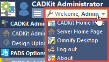
The title menu allows you to navigate to other applications as well as log out of the CADKit Administrator. The CADKit Administrator contains the following data pages:
| Page | Description |
|---|---|
| PADS Field Mapping | Define which Empower fields will be assigned as attributes and key fields in PADS Logic |
| PADS Views/Filters | Define filters to simplify searching when adding or updating PADS Logic components |
| PADS Rules | Define loading and BOM creation component rules |
| Altium Field Mapping | Define which Empower fields will be assigned as attributes and key fields in Altium Designer |
| Altium Views/Filters | Define filters to simplify searching when adding or updating Altium Designer components |
| Altium Rules | Define loading and BOM creation component rules |
| SOLIDWORKS Options | Define key field mapping and loading rules for the SolidWorks adapter |
| Solidedge Options | Define key field mapping and loading rules for the Solidedge adapter |
| Document Options | Define default options for the document upload/check-in features of CADKit |
| Design Upload Settings | Define configurations for the Design Upload Utility |
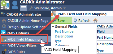
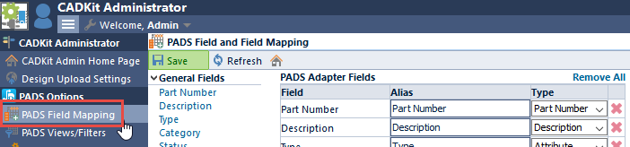
PADS Field Mapping
The PADS Field Mapping page allows you to define which Empower fields will be assigned as attributes and key fields in PADS Logic.
The page will list all available Empower fields that can be assigned attributes and key fields for PADS Logic schematic components. The PADS Logic adapter allows you to assign each schematic component to a matching Item in the Empower database. For the adapter to match a schematic component to an Empower Item, the Part Number field must be assigned as an attribute to the schematic component. When adding or updating schematic components, the Adapter will automatically assign the attributes specified on this page of the CADKit Administrator. When defining fields that the Adapter will use, you will be able to select: General fields (e.g. Part Number, Description, Type, etc.), Attribute fields, and Vendor fields (Vendor name and part number).
This page allows you to define all fields that can be used by the Adapter. However, you can disable fields by creating separate "Views" for the adapter (see next session).
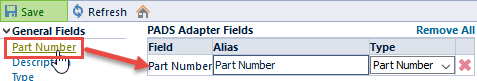
To enable a field to be used by the adapter, click the field name in the Available fields list. This will add the field to the PADS Adapter Fields list.
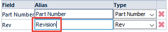
Once the field has been placed in the PADS Adapter Fields list, you will be able to define a field Alias. The Alias will be the name that appears in the Adapter, as well as the attribute name assigned to the component in the schematic.
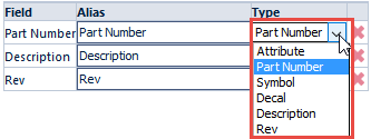
For each enabled field, you will be able to define the field Type as one of the following:
| Type | Description |
|---|---|
| Attribute | Field will be used as a standard attribute field on the schematic component |
| Part Number | Defines the field that contains the Empower Part Number (used when verifying designs and uploading BOMs) |
| Symbol | Defines the field that contains the PADS Logic Part Type/Symbol |
| Decal | Defines the field that contains the PADS Decal |
| Description | Used as a standard attribute field on the schematic component and displayed when creating BOMs from the schematic |
| Rev | Used as a standard attribute field on the schematic component and displayed when creating BOMs from the schematic |
PADS Views/Filters
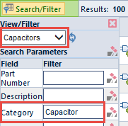
The PADS Field Mapping page allows you to define all Empower fields that will be used by the PADS Logic adapter. You can also define "Views" that allow you to define default field search parameters as well as hide and reorder the way fields are presented in the adapter. To define "Views" select the PADS Views/Filters page option.
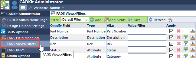
The PADS Views/Filters page lists all defined views in the Filter drop list. Note: the Filter list will always contain a [Default Filter] option. This option represents the field configuration when no filters are selected.

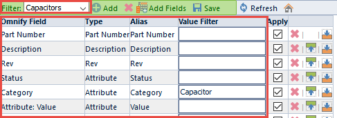
Once a filter is selected, the field list will display the file configuration for that view.
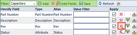
You can choose to eliminate fields from the search and apply list by clicking the Remove button.
You can define a default search parameter for any fields by assigning a value in the Value Filter field.
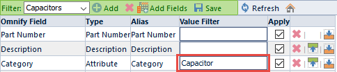
When the view is selected in the Adapter, the filter value will automatically be assigned.
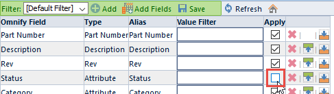
The Apply checkbox allows you to control whether or not the field will assign an attribute to the schematic component. If the Apply option is checked, users will be able to search on the field and the field will be applied as an attribute to the component. If the Apply option is unchecked, users will be able to search on the field, however, the field will not be applied as an attribute to the component.
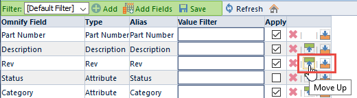
You can modify the field display order using the Move Up and Move Down icons.
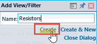
To create a new filter, click the Add icon on the Toolbar. This will display the New Filter slide-out panel.
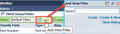
To define a new filter, specify the Filter name and then click the Create link.
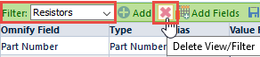
To remove a filter, select the filter from the Filter drop list, and then click the Remove Filter icon.
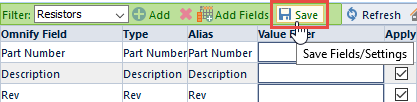
If you modify any of the field options in the list, click the Save toolbar button to store the settings for that particular filter.
PADS Rules
The PADS Rules page allows you to define rules to be applied when loading, validating, and creating BOMs from PADS Logic schematic. To define Rules select the PADS Rules page option.
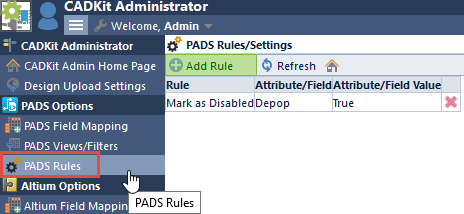
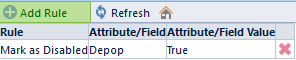
The page will list all defined rules.
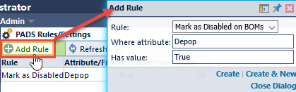
To add a rule, click the Add Rule toolbar button. This will display the New Rule slide-out panel.
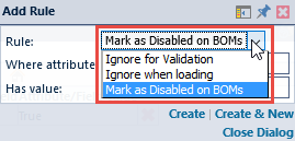
When defining a rule, you can create one of the following types of rules:
| Rule Type | Description |
|---|---|
| Ignore for Validation | If the component has the assigned attribute, the component will not appear when validating the design |
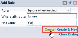
| Ignore when loading | If the component has the assigned attribute, the component will not be loaded for updates or when creating a BOM from the schematic |
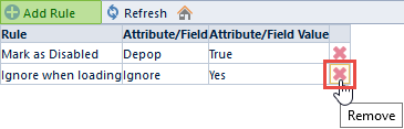
| Mark as Disabled on BOMs | If the component has the assigned attribute, the component will be assigned as a "Disabled" item when creating a BOM from the schematic |
When defining a rule, you must define an attribute name and value. To create the rule, click the Create or Create & New links. Note: clicking Create will create the rule and close the slide-out panel, clicking Create & New will create the rule and keep the slide-out panel open.
To remove/delete a rule, click the Delete Rule icon on the rule list.
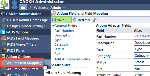
Altium Field Mapping
The Altium Field Mapping page allows you to define which Empower fields will be assigned as attributes and key fields in Altium Designer.
The page will list all available Empower fields that can be assigned attributes and key fields for Altium Designer schematic components. The Altium Designer adapter allows you to assign each schematic component to a matching Item in the Empower database. For the adapter to match a schematic component to an Empower Item, the Part Number field must be assigned as an attribute to the schematic component. When adding or updating schematic components, the Adapter will automatically assign the attributes specified on this page of the CADKit Administrator. When defining fields that the Adapter will use, you will be able to select: General fields (e.g. Part Number, Description, Type, etc.), Attribute fields, and Vendor fields (Vendor name and part number).
This page allows you to define all fields that can be used by the Adapter. However, you can disable fields by creating separate "Views" for the adapter (see next session).
To enable a field to be used by the adapter, click the field name in the Available fields list. This will add the field to the Altium Adapter Fields list.
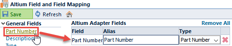
Once the field has been placed in the Altium Adapter Fields list, you will be able to define a field Alias. The Alias will be the name that appears in the Adapter, as well as the attribute name assigned to the component in the schematic.
For each enabled field, you will be able to define the field Type as one of the following:
| Type | Description |
|---|---|
| Attribute | Field will be used as a standard attribute field on the schematic component |
| Part Number | Defines the field that contains the Empower Part Number (used when verifying designs and uploading BOMs) |
| Symbol | Defines the field that contains the Altium Designer Symbol |
| Description | Used as a standard attribute field on the schematic component and displayed when creating BOMs from the schematic |
| Rev | Used as a standard attribute field on the schematic component and displayed when creating BOMs from the schematic |
Altium Views/Filters
The Altium Field Mapping page allows you to define all Empower fields that will be used by the Altium adapter. You can also define "Views" that allow you to define default field search parameters as well as hide and reorder the way fields are presented in the adapter. To define "Views" select the Altium Views/Filters page option.
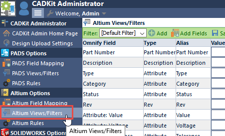
The Altium Views/Filters page lists all defined views in the Filter drop list. Note: the Filter list will always contain a [Default Filter] option. This option represents the field configuration when no filters are selected.
Once a filter is selected, the field list will display the file configuration for that view.
You can choose to eliminate fields from the search and apply list by clicking the Remove button.
You can define a default search parameter for any fields by assigning a value in the Value Filter field.
When the view is selected in the Adapter, the filter value will automatically be assigned.
The Apply checkbox allows you to control whether or not the field will assign an attribute to the schematic component. If the Apply option is checked, users will be able to search on the field and the field will be applied as an attribute to the component. If the Apply option is unchecked, users will be able to search on the field, however, the field will not be applied as an attribute to the component.
You can modify the field display order using the Move Up and Move Down icons.
To create a new filter, click the Add icon on the Toolbar. This will display the New Filter slide-out panel.
To define a new filter, specify the Filter name and then click the Create link.
To remove a filter, select the filter from the Filter drop list, and then click the Remove Filter icon.
If you modify any of the field options in the list, click the Save toolbar button to store the settings for that particular filter.
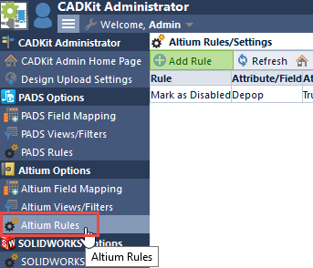
Altium Rules
The Altium Rules page allows you to define rules to be applied when loading, validating, and creating BOMs from Altium Designer schematic. To define Rules select the Altium Rules page option.
The page will list all defined rules.
o add a rule, click the Add Rule toolbar button. This will display the New Rule slide-out panel.
When defining a rule, you can create one of the following types of rules:
| Rule Type | Description |
|---|---|
| Ignore for Validation | If the component has the assigned attribute, the component will not appear when validating the design |
| Ignore when loading | If the component has the assigned attribute, the component will not be loaded for updates or when creating a BOM from the schematic |
| Mark as Disabled on BOMs | If the component has the assigned attribute, the component will be assigned as a "Disabled" item when creating a BOM from the schematic |
When defining a rule, you must define an attribute name and value. To create the rule, click the Create or Create & New links. Note: clicking Create will create the rule and close the slide-out panel, clicking Create & New will create the rule and keep the slide-out panel open.
To remove/delete a rule, click the Delete Rule icon on the rule list.
SOLIDWORKS Options
The SOLIDWORKS Options allows you to define key fields and options for the SOLIDWORKS Adapter. To define/modify SOLIDWORKS options, click the SOLIDWORKS Options page.
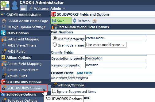
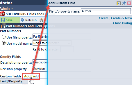
Part Numbers
CADKit links a SOLIDWORKS model/component to a unique Empower Item. To define how the Adapter will map the model to an Empower Item, you must use the Part Numbers section.
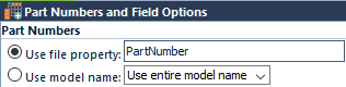
You can have CADKit determine the model Part Number either from the model file name or by a custom model property. To use a custom model property, click the Use file property option and then specify the property name.
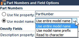
To use the model file name as the Part Number select the Use model name option.
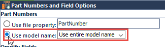
When using the model name, you will be able to select one of the following options:
| Option | Description |
|---|---|
| Use entire model name | If this option is selected, the system will use the entire model/file name as the part number |
| Use model name prefix | If this option is selected, the system will use the first characters of the model/file name as the part number. You will be able to define how many characters to read. 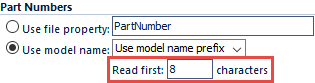 |
| Read to character | If this option is selected, the system will use the first characters of the model/file name as the part number. You will be able to define the character to read to. 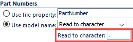 |
Empower Fields
The Empower Fields section allows you to map and read key fields. You can map Empower Rev and Description fields to specific model/file properties.

These fields will appear when loading an assembly in the Adapter.
Custom Fields
You can define additional fields to be displayed in the Adapter, by adding fields to the Custom Fields section.

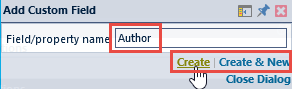
To add a field, click the Add Field button. This will display the Custom Field slide-out panel.
To define a custom field, specify the model/file property name, and then click the Create or Create & New button.
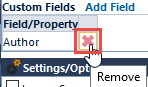
To remove a field, click the Delete Field button.
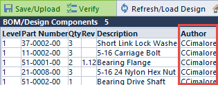
Fields that appear in this list, will be displayed in the Adapter when loading the assembly.
Settings/Options
The Settings/Options section provides the following settings:

| Option | Description |
|---|---|
| Ignore suppressed items | If enabled, CADKit will ignore "suppressed" items in the assembly |
| Ignore hidden items | If enabled, CADKit will ignore items tagged as "hidden" (new versions of SOLIDWORKS) |
| Ignore items that are not loaded | If enabled, CADKit will ignore design components that have not been loaded in the current configuration |
| Stop reading items at level | Allows you to ignore loading items under a specified level of hierarchy |
Ignore Items
You can also ignore items based on model/file properties. To create a custom ignore rule, click the Add Rule button in the Ignore Items section.

This will display the Ignore Items slide-out panel.
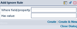
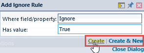
When defining a rule, you will be able to define the model/file property name and value. To define a rule, specify the name and value and then click the Create or Create & New button.
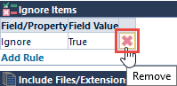
To remove a rule, click the Delete Rule icon.
Include File Extensions
The Include File Extensions section allows you to define a set of file extensions that will be read when the Adapter reads the associated files when uploading documents. Using these settings, the system will search for similar file names as used with the models and assembly files, and include them in the upload list.
If you wanted to have the Adapter search for all PDF files that match the assembly and model files, you could add pdf to the Include File Extensions list. The system would then search for the following files:
C:\Development\SampleAssembly\01-0000-00.pdf
C:\Development\SampleAssembly\02-0001-00.pdf
If either (or both) files were found, those files would be included in the upload file list.
For more information on uploading files, refer to the Document Upload section of the specific Adapter section of this manual.
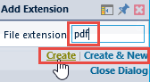
To add a file extension to search for, click the Add button. This will open the Include File Extension slide-out panel.
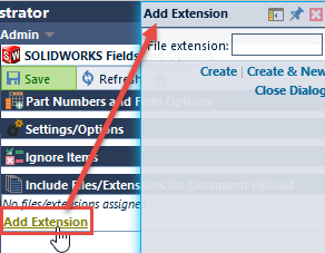
To add an extension to the list, specify the file extension and then click the Create or Create & New link.
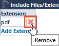
To remove an extension, click the Delete icon in the list.
Solidedge Options
The Solidedge Options allows you to define key fields and options for the Solidedge Adapter. To define/modify Solidedge options, click the Solid Edge Options page.
Part Numbers
CADKit links a Solidedge model/component to a unique Empower Item. To define how the Adapter will map the model to an Empower Item, you must use the Part Numbers section.
You can have CADKit determine the model Part Number either from the model file name or by a custom model property. To use a custom model property, click the Use file property option and then specify the property name.
To use the model file name as the Part Number select the Use model name option.
When using the model name, you will be able to select one of the following options:
| Option | Description |
|---|---|
| Use entire model name | If this option is selected, the system will use the entire model/file name as the part number |
| Use model name prefix | If this option is selected, the system will use the first characters of the model/file name as the part number. You will be able to define how many characters to read. |
| Read to character | If this option is selected, the system will use the first characters of the model/file name as the part number. You will be able to define the character to read to. |
Empower Fields
The Empower Fields section allows you to map and read key fields. You can map Empower Rev and Description fields to specific model/file properties.
These fields will appear when loading an assembly in the Adapter.
Custom Fields
You can define additional fields to be displayed in the Adapter, by adding fields to the Custom Fields section.
To add a field, click the Add Field button. This will display the Custom Field slide-out panel.
To define a custom field, specify the model/file property name, and then click the Create or Create & New button.
To remove a field, click the Delete Field button.
Fields that appear in this list, will be displayed in the Adapter when loading the assembly.
Settings/Options
The Settings/Options section provides the following settings:

| Option | Description |
|---|---|
| Ignore Hardware items | If enabled, CADKit will ignore items tagged as "Hardware" |
| Ignore hidden items | If enabled, CADKit will ignore items tagged as "hidden" |
| Stop reading items at level | Allows you to ignore loading items under a specified level of hierarchy |
Ignore Items
You can also ignore items based on model/file properties. To create a custom ignore rule, click the Add Rule button in the Ignore Items section.
This will display the Ignore Items slide-out panel.
When defining a rule, you will be able to define the model/file property name and value. To define a rule, specify the name and value and then click the Create or Create & New button.
To remove a rule, click the Delete Rule icon.
Include File Extensions
The Include File Extensions section allows you to define a set of file extensions that will be read when the Adapter reads the associated files when uploading documents. Using these settings, the system will search for similar file names as used with the models and assembly files, and include them in the upload list.
For example, an assembly consists of the following files:
- C:\Development\SampleAssembly\01-0000-00.asm (Assembly)
- C:\Development\SampleAssembly\02-0001-00.par (Model)
If you wanted to have the Adapter search for all PDF files that match the assembly and model files, you could add pdf to the Include File Extensions list. The system would then search for the following files:
- C:\Development\SampleAssembly\01-0000-00.pdf
- C:\Development\SampleAssembly\02-0001-00.pdf
If either (or both) files were found, those files would be included in the upload file list.
For more information on uploading files, refer to the Document Upload section of the specific Adapter section of this manual.
To add a file extension to search for, click the Add button. This will open the Include File Extension slide-out panel.
To add an extension to the list, specify the file extension and then click the Create or Create & New link.
To remove an extension, click the Delete icon in the list.
Document Options
The Document Options allows you to define default file properties to be used when uploading files from the SolidWorks and Solid Edge Adapter. To define/modify default document options, click the Document Options page.
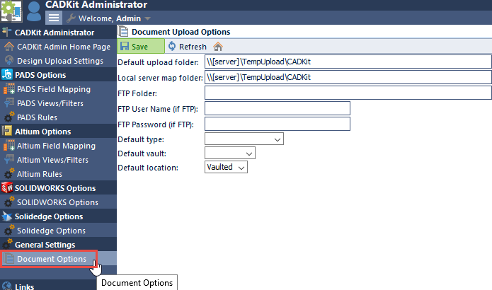
The Document Options allows you to set the following options:
| Option | Description |
|---|---|
| Default upload folder | This option will be used by the client tools to specify the write area/folder that will receive the files. |
| Local server map folder | This setting will represent the upload folder as seen by the Empower Web Server |
| FTP Folder | If you wish to have the files uploaded to a FTP site, this option will represent the path to the FTP site. |
| FTP User Name | If you are using FTP, set this option to define the User Name for authentication on the FTP Site |
| FTP Password | If you are using FTP, set this option to define the User Password for authentication on the FTP Site |
| Default type | Allows you to select the default document type that will be assigned to uploaded documents |
| Default vault | Allows you to select the default document vault that will be assigned to uploaded documents |
| Default location | Allows you to select the default location (either Linked or Vaulted) |
Note: these options represent the default settings. You will be able to modify the properties on each file during the upload process.
Design Upload
The CADKit Design Upload Utility provides users with a simply manner to upload information from various sources (such as MCAD, ECAD, manually created files, etc.). The Design Upload Utility will guide the users through the upload process. The Design Upload Utility allows administrators to create various "Configurations".
Each configuration allows you to define specific data sets (such as BOM, design files, etc.) to help guide users through the design upload process.
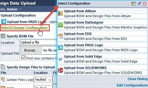
You can launch the Design Upload Utility from the CADKit links on the Server Home Page.
From the Design Upload Utility, you can select a Configuration by clicking the Select/Change Configuration button.
You can define/modify Configurations in the CADKit Administrator.
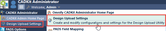
Adding/Editing Configurations
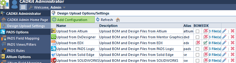
To add or modify configurations, click the Add or Edit buttons.
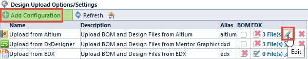
This will present the Configuration Properties panel.
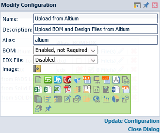
When adding/editing configurations, you will be able to define:
| Field | Description |
|---|---|
| Name | Configuration name |
| Description | Full description of configuration |
| Alias | Configuration alias (can be used as URL query string/parameter) |
| BOM | Define if a BOM file is required/requested |
| EDX File | Define if an EDX file is required/requested |
| Image | Icon for the profile |
With BOM and EDX files, you will be able to define:
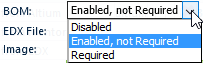
| Setting | Description |
|---|---|
| Disabled | BOM file option will not be displayed |
| Enabled, not Required | BOM file option will be displayed, but the user will not be required to upload a BOM file |
| Required | The user will be required to upload a BOM file |
Configuration Files
Configurations can contain an unlimited number of files that can be uploaded when using the utility. To modify the file list, click the Files link on the configuration.
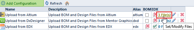
This will present the Modify Configuration Files panel.
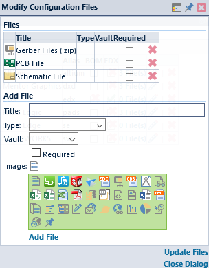
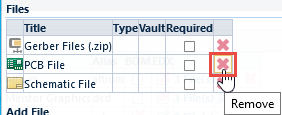
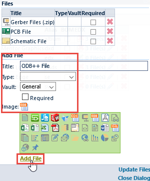
To add a file, define the name, default type, default vault, and image. Click the Add File button to add the file to the Files list.
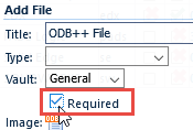
When defining a file, you can set the file to be required. Required files must be specified for the user to advance the wizard.
To remove a file, click the Remove button.